Skip to content
Feeders or transmission lines are used to transfer RF signals from one point to another. They are used in many areas, one common example of an RF feeder is the coax or coaxial cable used to connect a television antenna to the television. The loss that a feeder introduces between the antenna and receiver or transmitter is of the utmost importance. Any power that it loses will reduce the efficiency of the station. In order to reduce this low loss types of coax are almost always used at these frequencies. These coax cables are thicker than the standard types.
Types of feeder:
There are several forms of feeder that can be used to transfer radio signals from one point to another. Each of these types of feeder has its own advantages and can be used to its best in different applications. They are all described in more details below:
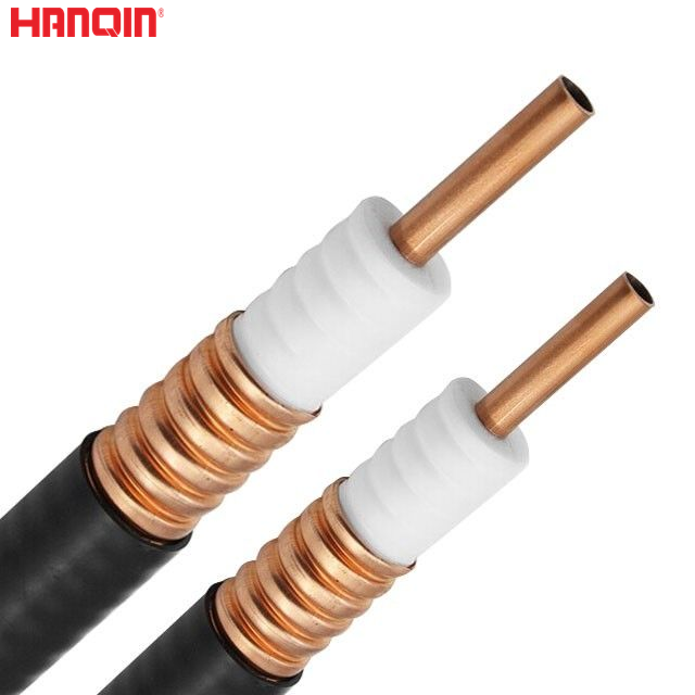
1.Coax or coaxial cable Coax cable is the most widely used radio frequency feeder being used in very many domestic and commercial applications. It consists of an inner conductor surrounded by an insulating dielectric and covered with an outer screen or braid. In turn there is a final insulation cover to act as protection. It carries current in both inner and outer conductors, but because they are equal and opposite all the fields are confined to within the cable and cannot radiate. As there are no fields outside the cable, nearby objects do not effect its properties and it can be used to carry RF energy through many locations with little risk of them being affected.
2.Waveguide: Another form of feeder which can be used at higher frequencies, particularly in the microwave region is called waveguide. Essentially it consists of a “pipe” which is usually rectangular in cross section, although occasionally circular ones are used.
Unlike coax cable, waveguide has no centre conductor, and the way it operates is different. A signal is launched or transmitted into it and as it cannot escape through the walls it travels along the waveguide. It is found that a waveguide of particular dimensions cannot operate below a certain frequency, having what is known as a cut-off frequency. Below this no signals propagate along it. This means that a number of different sizes of waveguide are available dependent on the frequency in use. These sizes are standardised and given numbers in the form WG**. As an example, a waveguide for use between 2.60 and 3.95 GHz has internal dimensions of 72 x 34 mm and is given the designation WG10.
The main advantage of waveguide is its low loss at high frequencies compared with coax. In the case of WG10 made from aluminium it can be as low as 0.7 dB per 30 metres. Against this its cost is much higher.
DATA SHEET: